Technorati Profile
This is done for the uses of "claiming" this blog via Technorati. Does anyone even USE that thing?
Monday, December 11, 2006
Fun: Gunnplexer Radar Components
So, what's available for radar components on the open market? Most radar guns (aka cheap hardware) is either in the 10GHz band or the 24GHz band. These high frequencies are also used by ham radio operators, so they sometimes try to use these as high bandwidth line of sight radio links.
So, where to get them?
IF you want new, expect to pay $500 to $1000 per node. Advanced Reciever is one that lets you know without requesting a quote.
How about used?
Well, depending on availability, you can assemble much of the parts you need from SHF Micro.
So, my friend Creuzer was wondering about interesting feedback effects versus police radar, so let's go over what you'd have to do. Police radar works purely on doppler effect. Gunnplexers use a pair of tuned diodes to produce a beat frequency from a continuous wave source, so speed is a simple conversion of output frequency to speed. Now, how do you play games with one?
If the police radar is "dumb" (common), the radar electronics will lock onto the most powerful signal. Because your return is FAR more powerful than his reflection, you should win this fight. Now, the tricky part. You'd have to take in his signal, determine the initial doppler shift from knowing your own speed, and then fire off the right frequency to add or subtract whatever you want to to that radar signal.
A "smart" radar system (does it even exist?) that looks for a specific strength return requires more time and investment. You'd have to apply something (like, say SHF's Eccosorb AN-73) that will reduce your radar profile. Of course, you also have to protect the usually expensive components, which would require a good dielectric (radar transparent) coating of plastic over the top. You might also need to apply a fine metal mesh to your windows to keep the RF from bouncing off your head and back to the gun (and then you can control the radiant direction more). Anyway,
you'd have to take a power measurement and try to radiate back a certain percent of that. This would also help with the "dumb" radar but it's far more expense than it's worth.
Sounds simple? Well, it might be, but there's an issue. Radar gunnplexers tend to "float" their tuning all over the place within a 3GHz band, and you usually only have 100MHz or so of available bandwidth. So, know your police radar bands and hope they have it tuned! Mind you, the old hardware worked at either X band (10.5 to 10.55GHz) or K Band (24.05 to 24.24GHz). Relatively more modern hardware runs somewhere between 34.2 and 35.2GHz. I've only found one reference to these, and it was from Japan and cost about $3000 per unit if my translation is right. 35GHz is becoming more common, though, I've seen a lot of miniature radar units (for UAVs) being built around hardware at this frequency.
And that is why I don't mind spilling this little tidbit. Unless your local police is using hardware from the 80's (they might be though!), you'll probably never be able to mess with their readings.
Tuesday, December 05, 2006
Fun Thoughts: Bad Drivers
I've read several traffic related stories lately, mostly about the new tailgate detecting laser system deployed in Airzona. Interesting, but I thought of a far more interesting result.
Everyone seems to have a cartop cargo pod these days. How about we spruce one up?
First, bolt on a few fiberglass Sidewinder lookalikes. I'd probably modify them so you can point one forward and one behind. Add cones to the engine are to both disguise the fake-ness and help with the aerodynamics.
Second, put a couple of windows in the front and rear. Behind these put a surplus 10GHz or 24GHz Gunnplexer and horn (the core waveguide of most police radars) and a 905nm IR laser with optics to provide a flat cone (police laser radar). This will let you light up someone's life if they're the speedy paranoid type or the annoying tailgater. This will have no effect on those who don't have radar detectors. I'd probably have to add in an LED system in the missile "nosecones" that would pulse in time with the radar pulse. Wonder what people would notice and believe from the movies...
Now, add a custom "I support direct application of traffic law" bumper sticker and some fake (or real) vehicle battle scars, and you'll have yourself a winner.
Not a cheap project. Figure $50-100 per emitter, plus the cargo carrier plus the missiles and mounts. You'll probably end up spending $1000 on this toy in the end.
A lot of space will still be available. What to do with it?
Careful design would allow you to place an automotive PC plus a bunch of sensors up top. Hook up a lot of cameras and you could provide a 360 degree tour (plus traffic stops by curious cops!). You could also run an algorithm to track speeders and get actual speed from them (it'd take some additional circuitry on the gunnplexers). A dedicated computer controlled pan-tilt-zoom camera turret would let you get a REAL good photo of them, too. GPS would be an obvious addition, too.
Now, silly and probably (highly) illegal stuff. Drill out and place LOTS of RGB LEDs in the exterior. Almost invisible when off, you could give yourself whatever lights you'd want depending on the control program. Keep the top clear and put a plastic bubble on top with a fake (or real) radar antenna spinning in it. THAT would get some attention. Maybe you could claim it's a weather radar? I know some people would actually want the missiles on the side to shoot, but I cannot condone that, nor having a mine dropper in the back to bomb that tailgater with grenades/caltrops/deer carcasses.
Wednesday, November 08, 2006
Sensors: Ultrasonic Phased Array
So, with the laser system falling through, I've been looking around at alternate distance measurements. Hence, ultrasonic. This isn't your typical sonar arrangement, though.
Your typical sonar system is composed of two ultrasonic transducers and associated electronics. One is used to transmit, one is used for recieve. Higher end units use one transducer (still figuring it out) and usually have closer range requirements. I'd like to build this one-transducer arrangement. Another issue/advantage to sonar is the wide detection spread. Some units can sense everything within a 90 degree cone, or so. Good if you're looking for ANYTHING, bad if you're looking for SOMETHING. Transducer frequency varies with size (smaller = tighter pattern). Some higher frequency ones (commonly 235KHz) have a much narrower cone, also.
I have a 25 KHz transducer, and might get my hands on a few 40KHz models. So, the pattern will be exceptionally wide. Cheap, though. So, how to counteract this? We turn to technology to do some cool effects?
Modern radar often times uses a phased array instead of mechanical means to slew the radar beam. A phased array is made up of many small radar units. These units have their signals carefully timed to generate specific phase relationships across the entire antenna. Due to the constructive/destructive nature of waves, this can be used to both combine the power of the antenna units and to focus the useful energy into a single beam. It also allows the unit to both be redundant and to electronically steer the beam path just by adjusting the phase from antenna to antenna.
Modern sonar also uses it, but in different ways. There may be a single sound source, but an array of recievers is used to detect the signal, allowing the arrival time and phase difference from each sensor to successfuly determine the direction and range (if active) of the target. This method is also used in modernday medical ultrasound to allow a 3D map to be generated from all the responses. We're looking at quite the DSP problem, though!
Considering I haven't found any hobbyist doing this, I thought it'd be nice to attempt to build a modular sonar array that can be configured to have any and all units be phase-related transmitters and recievers. I could control the whole thing via a CPLD, but my test unit will be based on a dsPIC probably.
The initial design will have single transducers (with associated filter and power electronics) placed on individual PCBs. Each PCB will have power, ground, digital in, digital out, analog in, analog out pins plus perhaps a serial port. The digital pins will allow a CPU to trigger and measure all recieved signals digitally, as most sonar units do. The analog pins will be there to let the user experiment with generating a cleaner analog frequency out and get the analog return. The transducers band-limit the signal, so the analog in may not be necessary. The analog out is more important as this could be coupled to a high speed ADC to allow more accurate phase measurements and to get certain signals out of the process (doppler shift, signal strength returns, etc). If some digitally programmed controls, like a digital pot, are used to control signal strength, a serial connection will also be supplied of the appropriate type. The individual boards have the advantage that you can reconfigure them to test out different transducer arrangements. They have the disadvantage of causing possible alignment difficulties that may result in bad results.
The CPU board would have headers for these boards. I could either generate the signals via PWM or output compare hardware. Returns would either go for input capture(CCP) or ADCs. Many dsPICs have a 500Ksps or 1Msps ADC with a 4 lane sample and hold system, allowing me to accurately measure 4 sensors at once. They also can have up to 8 PWMs and CCP units. In theory, this means that up to 4 analog signals or 8 digital signals could be processed at once. I think I'll start with 4 and go from there. I probably could do 8 analog signals at once at the speeds these ADCs work at without concern of being off too much (25Khz x8=200Khzx2=400Khz, so worst case is slightly better than the nyquist limit). Other architectures may be better for this (ARM people? AVR people?).
One idea for the mobile PC robot crowd is to use a 18F4550 PIC. These chips have a 200Ksps ADC and enough CCP units to possibly support a full 5 transducers. This data could be sent back on the USB bus for capture analysis inside a math program (I'm considering this myself for algorithm and hardware testing). After that, take what you've learned and put together a DSP algorithm for a dsPIC.
I think that this could result in quite exceptional sonar mapping with fairly low cost 1D, 2D, and 3D arrays.
Thoughts? Did I miss someone out there who's done this before?
Wednesday, November 01, 2006
Oops! The Laser Rangefinder
Why you need to research before buying parts...
I meant to build a laser rangefinder (see paper that drove this idea here).
I'd like to get away from having to frequency adjust the laser, so I run across an Erbium rod for $10. Even if it's too damaged to work, I'm not out much. Now, my research into Erbium is that it's used in eye-safe lasers with a wavelength of 1.5um. Wonderful. It's on order and shipped as I type this.
Unfortunately, there's two types of Erbium doped rods. One is Erbium:Glass, with a pinkish color. This does the 1.5um lasing. Then there's Erbium:YAG. More expensive, it does 2.9um (half the frequency). It's greenish. See the link above? Yep, it's greenish. Unless they have a different color, I think I was shot down before I even started. There goes my "simple laser pulse". I also ordered several spare supposedly laser optics and several displosable flash units. Guess that means I'll have $20 or so in hardware sitting in my parts boxes for a while.
Now, depending on if the lasing rod lucks out in damage, I COULD try and get the rest of the parts, but I suspect it'd be cheaper for me to track down an Er:Glass rod than to get the frequency doubling crystal (KTP or KTA perhaps? I need a good laser handbook).
HMD: Where to get parts, what's new, what's soon
I'm trying to head back to the land of the electronic for a while, with that, however...
I decided to poke my nose into head mounted displays. I've always wanted to have a small glasses or otherwise transparently mounted information display. Not all the time, but enough. With my service job, being able to display the readout of my DMM or oscilloscope directly into my vision would be absolutely fantastic.
So, what's available?
Let's start with the "near mortal" components.
Myvu
Ignore the marketing images, they don't do this product justice. This is perhaps the finest binocular HMD available. $400 is a bit steep for a QVGA display headset, but don't let the Star Trek visor design fool you. Micro Optical focuses on minimum occlusion display technology. That, translated, means it obscures as little of your vision as possible. This bar design allows you to see a lot above and below the displays, and the rest is actually tinted transparent, so you can see around the displays, too. The result? From the reviews I've read, it means you can actually wear them and use them without feeling any more strain on your eyes or stomach than a standard desktop LCD.
Apparently the design is rugged and lasts 6 hours on 3 AAA's (and the special IPod version runs on a custom lithium-ion in the special ipod case). The optics are a single fused block, so no worries about alignment.
3DVisor
Picking up where the original 3D headsets left off, 3DVisor is trying to bring high quality HMDs to a wider population. Yes, you do get the same disorientation issues as all enclosed HMDs provide. However, these aren't QVGA. These aren't VGA. Yes, they're full SVGA and have a VGA connector. Normally units of this resolution are $1000 to $2000. They're now selling this for $550. Rumor has it that they're going to be releasing an XGA (1024x768) model in the near future. Given that they were originally selling the current version for $900, the price break signals that both the OLED technology is maturing and that the future XGA model may break the $1000 barrier. XGA HMDs have been the realm of the military and research institutions and still traditionally cost as much if not more than a new car. I can't wait to see.
Now, parts
Kopin
I linked directly to their Cyberdisplay section. Kopin is behind many low cost HMD hardware designs. I wouldn't doubt many of their displays have shown up in the $200 bargain basement HMDs. I know their displays (black and white) have shown up in camera, kid's night vision, and currently kids nightvision on an R/C car.
Now, most of these were black and white components. While I love hacking, sometimes you have to start from scratch. And where does that get me? Kopin sells both the main components (LCD, backlight, driver chip) and prepackaged assemblies (monocle display, binocular displays) for QVGA and VGA. The QVGA monocle (no VGA version, though) interests me as a possible core component to building a HMD. No driver chip, so it's going to cost almost as much as the VGA binocular arrangement, but that's how things work. You get twice the product for half the price with HMDs.
And in the future?
Microvision
I ran across Microvision a year or so ago. At that time they were making high end HMDs for the military and had one $5000 red Nomad monocle. Sounds like a lot. They have a secret. They're the only group that I've seen that has an analog control 2D MEMS micromirror. I've seen the TI DLP hardware, that's pretty much a digital system, it's either pointing here, or pointing there. Microvision had used this to build the Nomad, and it let them put up any resolution they wanted to at extremely high framerates. Cost of the laser component and driver were the limiting factors. Apparently they've gotten over that. They're now working on integrating a fully working RGB laser MEMS projector system into things like car HUDs and cell phones. It's only a matter of time before the projector becomes available then. If it doesn't need any complex optics to work, this may be the best option to project an on-glass transparent HUD for a mobile user. The IPM looks quite small and hopefully inexpensive. Who knows, you might be able to pick up an XGA full color display for $100 at your local electronics shop in a year or two.
Saturday, October 28, 2006
Algorithm: JPEG and related
I've been researching image compression on and off for a while. I see the methods that make up JPEG forming a core standard that most modern image and video compression is based on.
I've been wanting to make a JPEG compressor in a dsPIC for a while now. What do you do when you only have 16K to 30K of RAM? You look at what you're doing!
JPEG takes a YCbCr image and compresses each channel separately. A block of 8x8 values is put through a discrete cosine transform (DCT) which, like the FFT, provides a frequency value. Next, there is a zig-zag pattern defined by JPEG that takes this 8x8 block and rearranges it into a linear 64 byte block. So far, if the DCT result is kept in a floating-point format, no data has been lost. Next up is quantization. Either a fixed multiplier sequence (simple) or one calculated from the overall image (complex) is used to scale the image data, losing resolution. After that, any data below a certain threshold is set to zero, which starts the compression. The final step is what's called Hufmann coding. It uses either a set or calculated table to assign a unique binary symbol (say 01 is one symble, and 011 is another symbol) to replace a part of data. The theory is that a symbol's length is inversely related to how often it shows up. Ideally the table should be generated beforehand from statistics, although on the fly table generation gets close. Both the Hufmann table and the quantization table need to be passed to the reader so that it may be effectively decoded.
It's a lot of information, but there are better and more in depth discussions on the net.
I have a camera that does VGA images. Standard output is 4:2:2 (I think that's the format). For every pixel, it puts out a greyscale 8 bit value and either a red or a blue 8 bit value.
So, I don't have to do any conversion. I can decimate the red and blue channels to bring it down to a 4:1:1 depth (4 greyscale per 1 of the color channels). To correctly capture this data, I need 8 lines stored in RAM. As a raw data count, that would be 10,240 bytes. After decimation that's 7,680 bytes. Might be a bit tight in there...
dsPICs have DMA, which makes it easy to get the data into buffers without CPU capture intervention. Since the 8x8 DCT is so common in image compression, people have been trying all SORTS of ways to get it fast and simple A single 8x8 DCT can be broken down into 16 1x8 DCTs. You run a DCT on each row, then one on each column. My plan is to run the DCT in place in the buffer on each row and put the results into a new buffer outside of DMA control. I can also sort the rows out to isolate the various channels at the same time. Once 8 rows have been read in for any channel buffer, the 1D column DCT can be run.
there are 40MHz TI DSPs that have DCT hardware for image processing, allowing them to do the rest of the compression in software. TI DSPs are great. I just don't want to fork over several grand for a compiler.
After that, I can immediately start making decisions. I don't necessarily need a full JPEG compatible image as long as I have a reader on the other end that can decode what I encode. One way suggested in a technical paper (find reference) is that the encoding stops at quantization and truncating the data. This is nearly as effective in compression as the Huffman table (both size and quality) and greatly reduces the additional workload required. High frequency information suffers greatly, however. I'm considering this method. given the extremely rapid data transfer that must be done for an embedded camera. I'd like to get a VGA or QVGA video compressed down small enough to stream over an RF link, but I believe that may be impossible given the horsepower I want to attempt it with. Time for a 200MHz ARM32?
Tools: CAD for the home user
I've recently started looking for good, no cost CAD software to work on my solids designs. I wanted to find something that's anyone can get and use continuously, so no expensive packages or time limited demos.
My original hunt lead me to open source. From there, I ran into the following software. I'm still just touching on these right now, so I might be missing the big picture.
BRL-CAD
BRL-CAD is an open source implementation of the Army Ballistics Research Laboratory solid modeling package. They use it to do simulations of various combat scenarios. Its results look pretty, but the Windows package I looked at shows that this is going to be a command line driven uphill battle. It's essentially a collection of very powerful software bits that can read and work on the same data set.
openCASCADE
Another CAD package, although this is not based on a US DoD project. Seems similar in capability to BRL-CAD, and also may be command line based. What got me interested in looking at this one is that it has close ties to various finite element analysis software packages.
Blender3D
Ah, an old open source 3D modelling standby. While you can do solid CAD style modelling with it, and it has a much better UI for diving into it than the prior two, it doesn't appear to do solid modeling, which may cause issues if you want to post-process the component.
Now, there's also a few "freebie" packages I'm investigating. As they're based on commercial packages for Windows, they tend to be at least easier to dive into within a few minutes. I'll have to see how everything stacks up in the long run.
Solidedge 2D V19
Basically the 2D component of SolidEdge, this is a really REALLY nice free 2D CAD package. It's not AutoCAD, but it reminds me of the fast and simple CAD package I learned on back in high school. It's also nice that it can open and edit all AutoCAD files, and can export into AutoCAD and MicroStation formats, so it's not locking you into its format.
Alibre Design Express
I'm just going through the initial tutorial for this one. If it's up there in capability with SolidWorks and SolidEdge, this one's a keeper. They've removed the ability to work with sheet metal forms and the ability to generate bill of materials (these are usually addons in other programs anyway). However, it looks like it's all there, I'll give it a try and I'll have to follow up on this at some point in the future.
Monday, October 23, 2006
The Fourth Combat Form: Nerf
As this blog's rolled on, I've talked a bit about three different combat teamplay concepts. MilesTAG (beefed up laser tag), paintball, and Airsoft. Well, to round out this, let's take a look at another obscure teamplay game, Nerf.
Most people (read kids, teenagers) get a few Nerf guns and play a few "shoot em" games with friends. A few go and modify their stock nerf guns to remove some of the safety limitations. A few others go and make their own cheap, custom rounds. Even fewer go and build their own guns, usually low shot PVC contraptions that, while ergonomic and effective (although sometimes really neither), they make a bullpup pneumatic potato launcher look sleek and sexy.
And then... there's a guy who goes by the pseudonym Boltsniper. I believe he's graduated with a mechanical engineering degree, like me. Unlike me, he exercises his 2nd amendment rights. He also uses that knowledge gained to make semi-automatic full custom Nerf designs that work.
I don't want to copy him, but I will learn from him. I still want to make that airsoft/paintball OICW. For that, I need to understand how shell load and eject systems work. Well, at least the loading system, as I've been contemplating a caseless design.
So, today's objectives?
Part 1: Figure out a caseless Nerf gun system that has a working magazine system and runs on 3/8" nano Stefan darts. 9.5mm caliber if true diameter.
Part 2: Take the magazine system and integrate it with an airsoft style motor driven plunger system. This will allow select fire and full auto to be implemented. I have no objection to Boltsniper's pump system at all. It's quite the marvel in terms of system understanding and parts availability. I just want to see if an airsoft style reciprocating assault rifle will work.
Project 2 will be scaling this up to 25mm for range tests and practicality testing on dummy airsoft airburst rounds.
And no, I haven't given up on MilesTAG2020. Frankly, the various systems all kinda melded together. My ultimate objective is a series of modules that connect together and can be used for various game types. MILES is just the "ultimate" use, as it will integrate the actual shot detection, scoring, and shooting into the module network. The problem is, like the real MILES, you can't simulate indirect fire or area effect attacks effectively. While not a big deal for a game system, the US Army's troops are not ready for the realities of full combat that includes shrapnel clouds. That realization was not mine originally, but belonged to some article I read. I fully agree with it, however.
Saturday, October 21, 2006
Near field active target tracking
Life got me. Busy summer, who knows if it's over yet...
I ran across a website a while ago about using a laser and photodiode to track a target in 3D.
http://www.k2.t.u-tokyo.ac.jp/fusion/LaserActiveTracking/
Now, they use a pair of galvanometers to control the laser. Nifty. You can build some yourself actually. It's mostly a magnet, glued to a shaft on bearings, over a magnetic coil. One end has a first surface mirror, the other has a feedback mechanism.
One issue with building galvanometers yourself is that you probably won't get anywhere NEAR the frequency response of a pro set. I know of a pro set for laser shows that runs $700 or so. That's less than half what most places would charge.
So, do we have alternatives? I believe yes. At the loss of flexibility and speed, we can probably use two standard RC servos for X-Y positioning. The high speed circle drawing could be replaced by a small motor with an off-kilter mirror. Now, to adjust circle size, either a small push rod to another servo-esque setup (worm gear?) or a different focusing mirror arrangement, I'll have to see what's pratical. A stripped laser pen diode should work fine for the source, and I can get a decently matched photodiode from Digikey et-al. Optics, motors, and other oddball stuff actually should be available locally for me at American Science and Surplus. Even the parts for a first run galvanometer if I so chose that route.
While the demonstrations they do are good, they have limitations. Power output and circle size is based upon relfected light from the target, and it's assumed to be roughly spherical. Makes adapting it to track other objects difficult. Not impossible. I'm more worried about tracking, say, my pasty white finger and then having one of my darker compatriots try it and the system thinking he's a meter farther back than he is. Time will tell. Maybe a slightly off-axis reciever running a 2D PSD (position sensitive device) would allow for rough triangulation and automatic tuning.
Friday, June 30, 2006
Blog Info
To that handful that has wandered across this blog, it appears that when I tested moderation months ago, I didn't save the notification email. Well, I just found my backlog, cleaned out the ads, and published everything else. I've removed moderation for now and now have enabled image verification. We'll try this for a while. I think I need to setup some other notification to... wonder if there's an anonymous email form...
ITX
Now, some of you are familiar with the Via Mini and Nano ITX boards. Nice boards running the Via C3/C7 series processors, 500MHz to 1.5GHz. Mini boards are 6x6 inches square and use "standard" PC components. Nano boards cost nearly twice as much and use laptop components. RAM prices for your desktop DDR2 and laptop SO-DIMM memory is about the same. I'd run the OS off a 4GB CF card connected to the IDE busses that are on both systems. Video is integrated. USB and firewire do also exist depending on the hardware setup. Some 3rd party variants have an expansion bus that can have cards added to give additonal serial ports, LAN ports, even a cardbus CF and PC card dual slot.
To make these things connectable as the core of my MILES2020 design, handling any 802.11g communication, doing video processing from a local camera, providing voice communication, possibly driving a HUD or other video display (wrist mounted map screen?). I planned a lot of this for individual microcontrollers, but some of that processing duty can be offset into an ITX system. Nano boards have a mini-PCI slot, mini have a standard PCI, so cards are available for both.
How to mount it? I figure middle of the back, within a molded case. A LION battery pack would be below it, in a similar protective housing and connected via a cable. A USB microcontroller would provide a link to a CAN bus. The hardwired ethernet connection provides a high bandwidth link to a camera module (maybe the MILES gun main MCU?) if used.
Any other ideas?
Thoughts?
Mobile Computing
Mobile computing is one of those sticky subjects. Modern mobile computing runs around as cell phones and PDAs. Then there's the crazy people working on a "wearable comping" system that keeps them partially in a computer generated world at all times.
I'm not THAT crazy. I look more for something resembling military computing. There when you need it, mostly hidden when not. One thing that popped up recently is a tech outline of a wearable PC. See link here:
http://www.eurotech.it/main/news.asp?2M=75
Now, I've run across enough hardware to consider how to build one. A base board system would distribute controls as needed. The main CPU would be a Gumstix, with video breakout and some extra IO. I'm hoping they have a lot of breakout of the video and input hardware. This could be hooked into a 2.2" touchscreen TFT screen ($50 from Mouser). The base board also has built in audio connectors. A 400MHz Gumstix running Linux may be powerful enough to run a voice recognition software package, providing hands free access. A subsystem microcontroller would control stuff like LEDs, IO, touchscreen, etc. I'd probably integrate a pseudo-IMU so that motion may be used to do some control, such as a mouse. I might also wire in a glove or something to allow controlled clicking, or move the IMU to the back of the hand there (now there's an idea...)
Depending on size, a LION battery set can be hidden either behind the board or elsewhere (depending on ergonomics and design). Now, final design is that the casing could be made to look rather professional with a vac-formed casing.
Thursday, June 29, 2006
Optical Tracking Idea Update
Well, it's been a while. I was thinking again today about the optical tracking and how to reduce the need for speed. What did I come up with?
Take a CPLD and feed an IR filtered Kodak 580fps B&W camera into it. Use a microcontroller to clock the whole operation (I still think a dsPIC30/33 is a good choice). Within the CPLD, do a comparison on each IR pixel byte to a programed byte threshold fed in from the PIC. If matched or exceeded (whatever is easier), output to a latching port that feeds the dsPIC and trip an interrupt line. By feeding through the line and frame syncs, too, you can setup a signal delay match to the data line. Now, the big idea here is that the PIC keeps count on what pixel should be output (use a Timer module?) and records this and the value whenever the threshold is exceeded.
While a simpler system based around just passing a go/no go signal would work, I'd like to have the imaging data, too. This would allow some filters to be built that adjust the sensor threshold depending on brightness. Another technique could be used to determine if the data recieved is a false response due to reflection, etc. If you're using the ultimate output to just track a beacon like I'd do, you could use moving target filters to keep the area watched small.
The big advantage of this setup over a direct link is that you can significantly reduce the image processing requirements. Another one is that it's still fully possible to do full frame captures without any additional overhead or need to "switch off" a software comparison module.
A disadvantage of this method is that it tosses yet another IC onto a video board I am hoping to keep small.
Saturday, May 06, 2006
Base Ideas: Optical Tracking
Sometimes ideas just pop in. Here's one for a basic optical beacon tracker that can possibly operate over extended ranges.
An optical tube (possible zoom, definitely close to focused to "infinity") has an array of IR phototransitors/photodiodes at one end. The target has an IR beacon (IR transmitter, probably driven by a fixed rate PWM from a microcontroller). By either just tracking which transistors are on, or in a more advanced variant, how much energy each sensor "reads" from the target (or if too many see it), the direction that the assembly has to be turned can be calculated. Power levels help to determine the "zoom" of the optics (if fitted). The PWM'ed signal allows either a hardware or software filter to be constructed to look specifically for the PWM signal (similar to the carrier frequency used in IRDA)
An optical tube (possible zoom, definitely close to focused to "infinity") has an array of IR phototransitors/photodiodes at one end. The target has an IR beacon (IR transmitter, probably driven by a fixed rate PWM from a microcontroller). By either just tracking which transistors are on, or in a more advanced variant, how much energy each sensor "reads" from the target (or if too many see it), the direction that the assembly has to be turned can be calculated. Power levels help to determine the "zoom" of the optics (if fitted). The PWM'ed signal allows either a hardware or software filter to be constructed to look specifically for the PWM signal (similar to the carrier frequency used in IRDA)
Tuesday, April 25, 2006
Open Servo and Camera
I just can't get a good PCB made for that camera socket. The one time I had something going, my last socket self destructed. Just can't get back in the saddle on that one...
Now, while I think on how to attack that again, I ran across OpenServo. Nice system. They're working on their second generation based on a mid range Atmel chip. Actually, this is fairly close to what I was planning for the CAN network. I was going to rebuild a high power/speed servo with a custom controller board and provide full servo functionality. Still going to, but I'll be overkilling it with a dsPIC.
Speaking of CAN, I'm STILL trying to work on the software stack for that.
Wednesday, March 01, 2006
Camera: A Sense of Scale
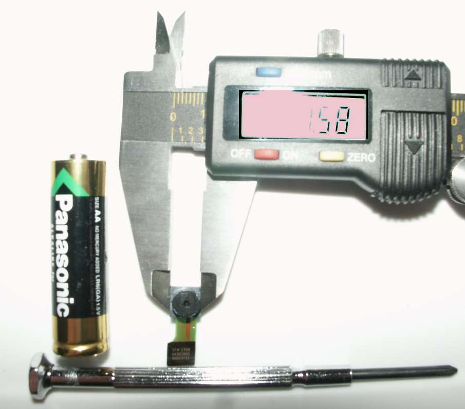
Well, I recieved my camera. I had issues getting a good picture of both the camera and the LCD. That is 7.58mm.
I really can't get a sense of scale until I have it in my hand. And that is TINY. The socket is about the size of a grain of rice and has a pitch of 0.4mm. That means 0.2mm of pad, and 0.2mm of space. That's roughly 8 mils each, about as fine as a normal hobbyist board house (say Sparkfun's BatchPCB ) will do. Scary.
Anyway, I'm planning on giving this one a try with home etching and soldering. I doubt I'll be able to get it without the mask, given the fine pitch, but who knows, it might work if I can figure out a mask or find out that a masking marker will work (temperature dependent).
Thursday, February 23, 2006
Sparkfun!
Sparkfun Electronics is a great site I've been poking around at for a long time. Just wish I could afford some of it.
Current wishlist that others might be interested in:
-Single transducer sonar unit with decent signal filtering onboard. Looks really nice.
-Various GPS units up the wazoo with lots of antenna options.
-Fully functional cell phone modules. Talk about tempting to build your own!
-Speaking of phones, they have a contest going on currently to figure out the hardware for their surplus, undocumented cameras from the Samsung E700.
-(I already have these) Affordable hot air rework and soldering stations. Quite useful
-accelerometers and gyros, ranging from single units to full IMU's. They are actually required to NOT sell the chips loose, but this is a decent way to get into the projects.
-Magnetic sensors for compass navigation.
I'm most interested in a small GPS module, a 3 axis mag sensor, and the sonar unit. That's about $170 worth of parts, so I'm afraid I have to hold off for a LONG while.
Saturday, February 18, 2006
Impact Mechanics
One of my odder interests are impact and protection. Slashdot recently ran an article with someone advocating using basically a memory foam for hardening armor. Now, I don't have a sample of memory foam right now, but I've seen Silly Putty and high density water-corn starch concoctions flow and move at one time and act like steel at a different time. I think that professional systems for impact absorption (special sparring suits) use a Neoprene outer shell, EVA underlay and a high density memory foam core, and probably similar layering going out the other side.
Now, WHY am I suddenly interested in this?
I've always got my mind on using stuff I build or want to build. I often wander back to Airsoft or Paintball as test grounds and play fields. Paint ball especially can HURT, so people wear armor. Now, most is fairly hard, but what if a lighter weight, fully pliable material was possible? Because it's local hardening, it should give more warning that you've been hit while still keeping the impact down. I've had a line of balls fired down my midsection before, it knocked the breath out of me. I'd have loved to have an inch or two of soft armor between me and them. Airsoft, due to the lower delivered energy, doesn't need to worry about this unless 25mm canister rounds start flying.
Thursday, February 16, 2006
CAN: Universal bus?
Well, I'm still learning gEDA. Finally got it loaded on a PC that I actually use. I got in my head a slightly modified version of my RC CAN interface. Instead of using a CAN enabled RC controller, how about a CAN enabled smart digital motor? I could then control the PID and rate control, increase accuracy, and have more information and control. So, this board should be designed to interface with the mechanics of the standard RC servo and replace it. So, I'm considering the following capabilities (no particular order):
Offboard support circuitry:
Now, onboard circuitry, preliminary part selections:
Now, another objective is using the Kodak 9630 camera chip and building a camera around it. It needs a 10MHz clock and 3.3V of power (sounds perfect for the MCP1252 above!). I'd configure it with the outputs buffered to work with whatever the logic is of the host processor. What's so special?
- H bridge based motor control
- Temperature measurement
- Input voltage measurement
- Module amperage measurement
- Programmable potentiometer for maximum position measurement
Offboard support circuitry:
- High current buck/boost controller: provides servos and modules with approximately 5V of regulated voltage, several amps of power (I hope). Keeps the electronics and servos electrically isolated from the main motor voltage spikes.
Now, onboard circuitry, preliminary part selections:
- PIC18F2580 (Microchip, QFN): integrated CAN, smallest board space for a CAN chip
- MCP1252-33x50 (Microchip, MSOP): Power regulator, will provide 5V 120mA for 2 to 5.5V input, may be replaced if a good alternative for 2.5V to 10V is found and also will phase out the buck/boost converter from some designs. Isolates electronics from servo voltage spikes.
- MCP2551 (Microchip, SOIC): CAN voltage converter (Requires 5V)
- MCP6S21 (Microchip, MSOP): PGA w/ SPI controls for measurement of the amperage via high side shunt, may need an external SPI delta sigma ADC
- MCP42100 (Microchip, TSSOP): Dual Digital Potentiometer w/ SPI controls. Used to scale line voltage to monitor raw 5V/high voltage line level, tune the high and low voltages of the position capture circuit to maximize accuracy.
- MCP9800 (Microchip, SOT): I2C temperature sensor, due to lower rate, may be software driven
Now, another objective is using the Kodak 9630 camera chip and building a camera around it. It needs a 10MHz clock and 3.3V of power (sounds perfect for the MCP1252 above!). I'd configure it with the outputs buffered to work with whatever the logic is of the host processor. What's so special?
- 8 bit B&W
- 126x98 pixels (approximately 12K of RAM required)
- Single shot and video modes
- 10MHz SPI (~90FPS) or 10MHz 8 bit parallel (~580FPS), plus H sync and V sync pins
- 16 pin interface expected (8 data, 2 I2C, ground, voltage, Vsync, Hsync, clock out, reset). Reset is also tied to the Power Good input of the camera.
- Possible variant: Replace the clock module with a crystal and PIC18, allow for slight variance in clock, some onboard processing, power control of an auto-focus/zoom lens onboard.
Subscribe to:
Posts (Atom)